For a few years I've been wanting to design my own mini badge for the SAINTCON conference badges. And this is the process I went through to finally build one.
At first I thought it would be fun to have my own badge to say I made, and seeing something I made in the history collection would be fun. I also wanted something I could use to exchange with members of the conference to collect more and unique mini-badges. Mostly, I wanted to learn what goes into designing and building a circuit board from scratch.
I saw that many mini-badges were essentially a few LEDs that highlighted a silkscreen design. But I didn't feel like I was artistic enough to make a good looking silkscreen, and I like building things that are functional.
Last year I was inspired by Redactd's mini-badge to build a mini-badge.
Redactd's mini-badge that was a small screen made of RGB LEDs, and it was a very sought after badge at SAINTCON.
The Screen Badge
My first attempt at a mini-badge was trying to build my own version of an RGB LED array using NeoPixel LEDs and an ATTINY84a as the chip. (Why an ATTINY84a? Because I had a few of them lying around and they are small)
Originally I tried the 2020 sized NeoPixels, but it seemed far from a "screen" of LEDs and more of just a few of them. It would have been hard to make any recognizable images out of the LEDs.
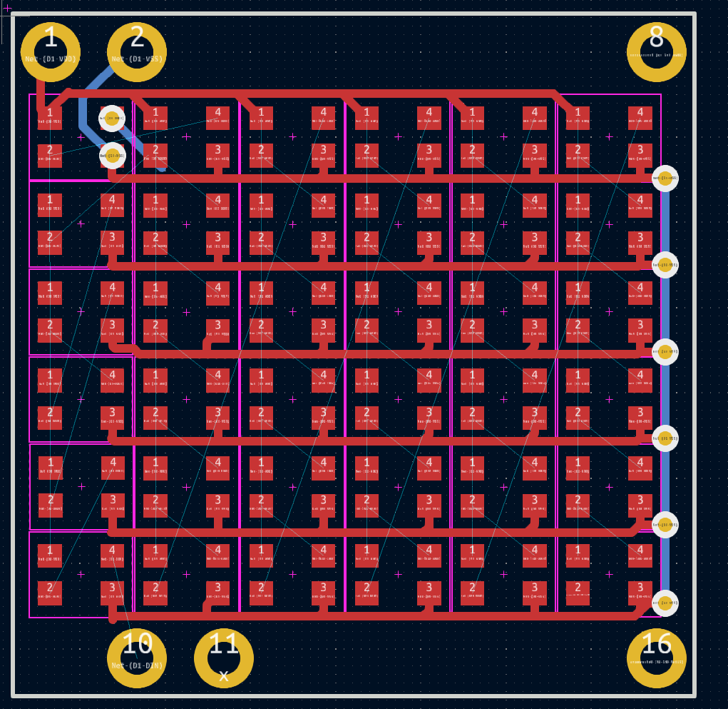
Shortly after I found some smaller 4492 LEDS that I was able to make much smaller to fit a few more LEDs on the board.
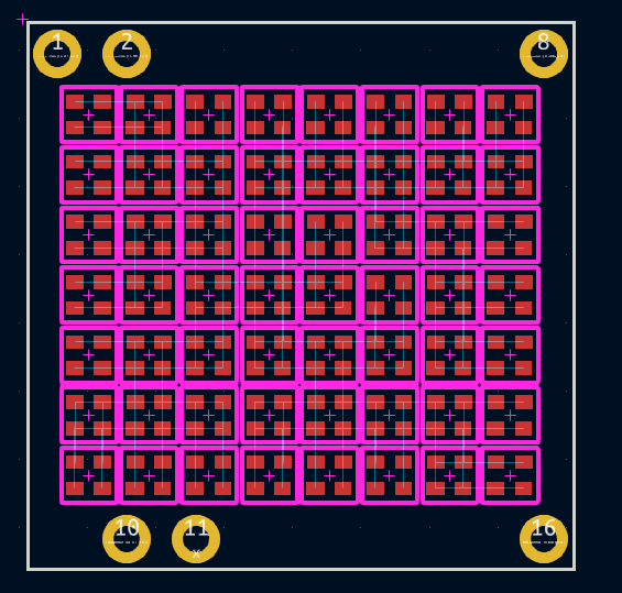
Even with this smaller LED form factor, it didn't feel quite as impressive as Redactd's badge. As I starting to think about the actual wiring with this format, I wasn't sure how I would run Power, ground, and link every LED to each other when the LEDs were this small. I was also set on soldering the badge together by hand, which in hind sight seems nearly impossible at this size.
The cost of the LEDs was quickly raising the price of the boards too. Each board was ~$23 in just the LEDs, then the additional costs of the microcontroller, PCB, and eventually the assembly costs. The design was quickly becoming a bit too much for a first mini badge.
SAINTSays Badge V1
I decided to take a step back and re-think the design of the mini-badge. I wanted something that was interesting enough, but was much simpler in components and wiring. From the 2023 SaintCON badge I was also inspired to learn the I2C protocol and to have my mini-badge communicate on the I2C bus. This also reinforced my goals to use an ATTINY84a on the badge since it could act as my I2C capable device. A few years back I had the idea to do a build a Simon Says style badge, and this seemed like a good time to revisit that idea since Simon Says only uses a few buttons and a few LEDs.
The LEDs flash in a pattern and the player repeats that pattern.
The pattern grows with each successful round, and the game ends when the player enters the wrong pattern.
The first revision of the SAINTSays mini-badge was a classic example of getting 80% of the way there takes 20% of the time. The badge had the basic connections for power, each LED was wired up along with the buttons.
The Learning curve was primarily in learning the KiCAD interface and how to place an order for a PCB from OSHPark.
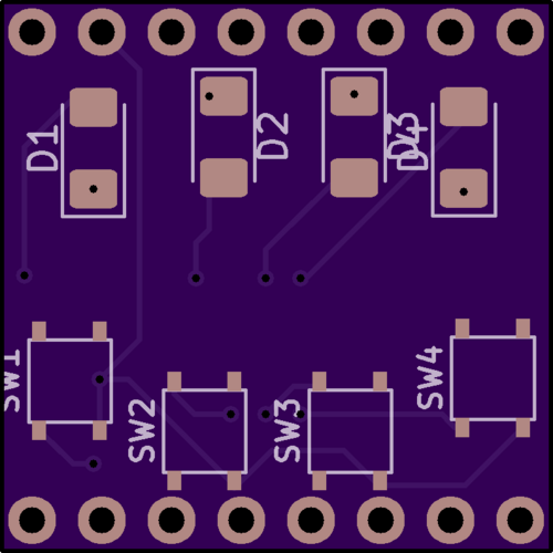
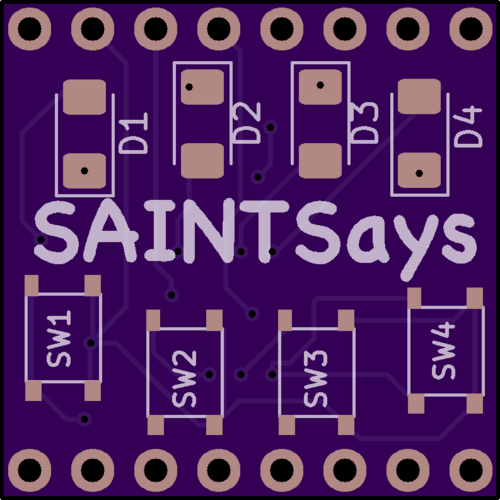
V1 PCB layout
That's not to say the first revision was perfect.
For starters, the LED ground wire was ran across all the LEDs, except the last 2 LEDs in the chain. This lead to only 1 of the LEDs working, but was easily resoled by running a small wire where the missing connection was at.
The most of the programming headers on the ATTINY84a were not ran to the programming pins on the mini-badge headers.
I initially attempted the same solution for the programming pins as I did with the LED ground wire, to run a small wire to connect everything
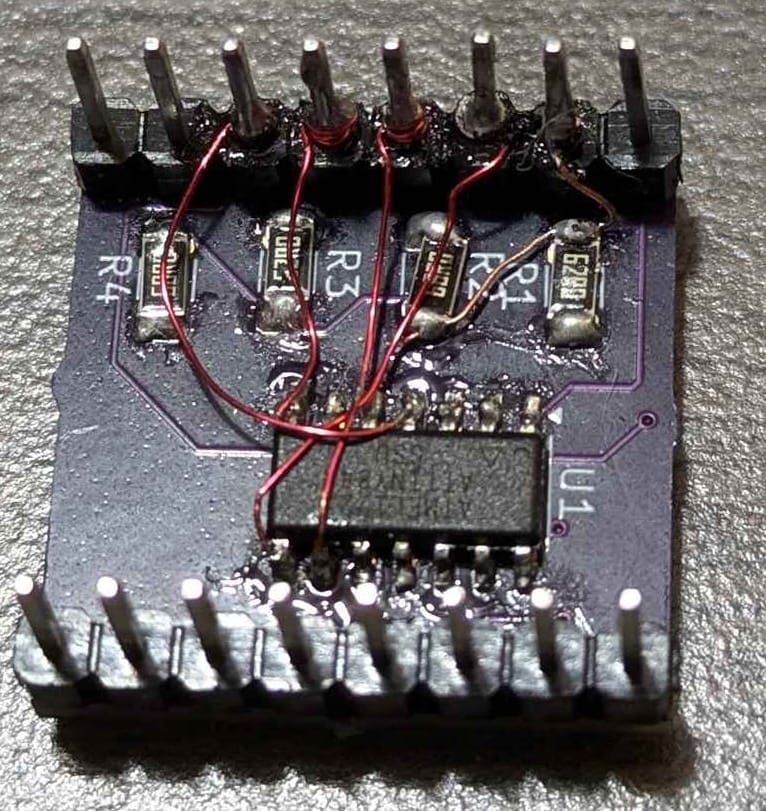
The soldering actually turned out rather clean for my own expectations, and a multimeter showed that the cables didn't cause any shorts.
Sadly, this soldering attempt didn't end up working, and I resorted to a chip clip to get the programming of the chip working.
I immediately noted some additional quality of life changes to the board I wanted to make as well.
The soldering pads for the buttons on the top were a little small, and required the pins of the buttons be bent inward to fit which also lifted the buttons off of the board.
The silkscreen labels of the Resistors were overlapping and could be a bit cleaner. Note that the strength of the resistors in this first version were only about 68 Ohms. I hadn't planned through the resistance needed yet, so i just picked a random resistor size I had laying around.
There was no labeling on the board and I forgot the ever important designer tag.
This was just a start to the issues but I knew I was already ready to design a v2 to address the programming pins and ground wire issues.
It takes a few weeks to get a set of board fabricated and shipped, so I immediately designed the v2 and got it ordered while I started working on the code.
SAINTSays Badge V2
The second version of the badge was ordered right when the great crowdstrike outage happened and it caused the badges to be shipped across the country before being redirected back to my house. This added a few more weeks to the shipping time, but surprisingly they still made it.
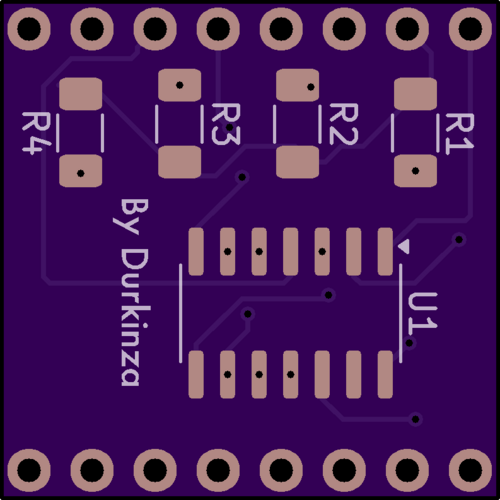
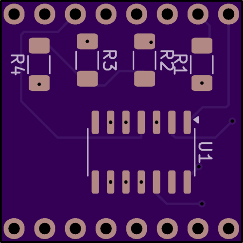
V2 PCB Layout
By the time the second version of the badge made it to my house I already had a "mostly" working code base for the badge.
SAINTSays Badge Code
I started by asking Chat GPT to write a Simon Says game for an arduino with 4 LEDs and 4 Buttons. While the basic structure of the game was there, the code was just not quite as workable as I had hoped.
I wanted this badge to be functional and feature full. Sure Simon Says was the main game, but what if there were others? What if the badge could display your score in the game? What if you wanted the badge to just flash pretty lights when you weren't playing the game?
There was so much potential with just 4 LEDs and buttons. Chat GPT's code did one thing, and it only did that one thing.
If the badge was going to support multiple games, it would need some sort of menu or mode that let you pick the game you wanted to play. It couldn't just throw you into Simon Says and expect you to know how to switch games.
So it needed to have a starting mode that wasn't the Game mode.
I knew that there needed to be a initial mode that the badge booted into that wasn't the game, and then the user could select the next mode they wanted to go to. This would need to be the "home menu" of sorts where all modes returned to.
This starting mode would also be used whenever the badge was "sleeping" to save battery. So "Sleep" mode it was called.
Well if there's a starting mode and a game mode, could there also be a way to change settings in the badge to customize it a bit? A settings mode?
There are 4 LEDs on the badge, so displaying the settings could be done where each LED is either On or Off for each of the respective settings.
This creates a natural limit of 4 settings, since there are only 4 LEDs. Scrolling through settings seemed difficult to design and complex to understand.
When in settings mode, if the user pressed a button, it would toggle the respective LED and setting. So settings need to be Binary of On or Off to keep it simple.
Since the badge wasn't doing anything in sleep mode, it would be a great place to show your high-score (in binary) on the LEDs, but also this could be turned off to save battery life in sleep mode. And the first setting was decided.
But how do you switch between modes?
Since Simon Says only ever required 1 button to be pressed at a time, I could use presses of multiple buttons simultaneously to act as triggers for switching modes. The settings mode also only required pressing 1 button at a time, so using multiple buttons together to indicate a "transition" worked out well.
From the sleep mode, if both outside buttons are pressed, that brought you to (and back from) the Settings mode.
If you wanted to start the game mode, just press any single button to launch that.
From the game if you press the outside buttons, it brought you back to the starting mode again.
SAINTSays Badge v3
By the time the code was mostly written, it was tested on the v2 of the mini-badge and there were some more quality of life improvements identified.
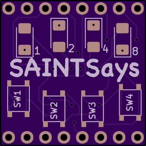
Now that there was a high-score display, it would help to indicate on the silkscreen what each LED represented in binary. In the case of this mini-badge the high-score is displayed in little-endian, meaning the "ones" place is on the left instead of the right.
Indicating the LED as 1,2,4,8 would help players see the direction of the score's display a bit easier.
But wait. Wasn't I2C part of the original goal of this project? There's no I2C pins even connected on the v1 and v2 badge.
In fact, once of the dedicated I2C pins that the ATTINY84a has is connected to a button. It can't even be connected to the I2C bus without causing issues every time a player presses a button.
A re-design of the chip layout was needed.
The SCL and SDA pins needed to be freed up to be on the I2C headers of the min-badge. Also, the ATTINY's Vcc pin was originally connected to the VBat header on the mini-badge. This means the chip would get a direct feed of power from the main badge's battery, which could be outside of the ATTINY's acceptable power range.
Since the wires were being re-ran anyway, it's best to move this Vcc pin to use the 3.3v header, This will ensure that the mini-badge will always get the voltage it can handle.
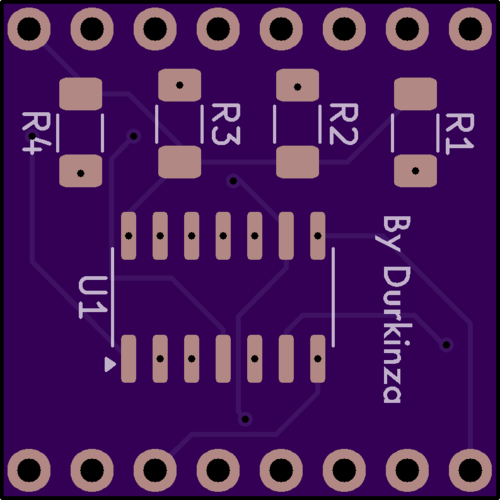
V3 Badge PCB Layout
The ATTINY ended up getting entirely turned around to accommodate the new pin layout. Also some of the drill holes have been lined up to be in the center of the resistor/LED pads. And the Clock header has been connected to a pin just for kicks. Maybe it could be useful in code update later on?
References
I primarily learned how to work on the badge in KiCad from the tutorial videos provided by SAINTCON, https://youtu.be/kkLfmo14oiQ
The video series goes through setting up the minibadge in KiCad down to ordering the badge in OSHpark's interface.
For the mini-badge spec, Luke's Github seems to still be the place to reference for the specifications of the badge layout
https://github.com/lukejenkins/minibadge
I tried a few different Arduino IDE libraries for programming the ATTINY84a.
Iniitally I started with attiny library, and I had a lot of success for my first few sketches with this library. But I could not get the "Wire.h" library (used for I2C setup) working when using this package, and I ended up having to switch because of that.
The ATTINYCore library has a custom Wire.h library written specifically for the ATTiny chipset, so this ended up working the best for my project. I did run into issues getting the BusPirate to work as a programmer with this library, as it didn't seem to support it, although it was listed in the project files?
I was able to compile the final hex code and upload it manually using Avrdude commands to work with the bus pirate.
Special Thanks!
Special thanks for the people that helped encourage me through the designing process and for testing the badge versions and game while it was being built.
Mav - For helping me with the badge design and for helping to keep the project sane.
Purvesta & P-Tasty - For testing the badge prototypes and helping debug code.
Kaylyn - For helping judge the solder-ability for new solder folks and helping clarify the user manual for the badge.
Comments
Write a comment ...