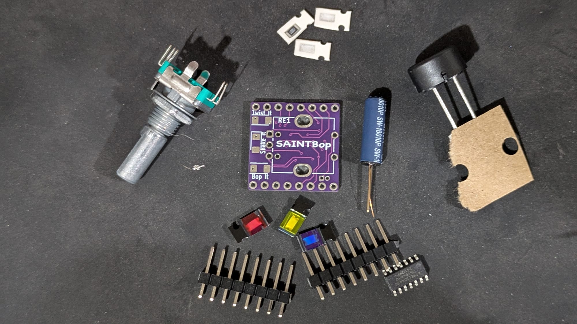
In each Saint Says package you should get a few components:
1 X Red LED
1 X Blue LED
1 X Yellow LED
1 X Green LED
4 X 510 Ohm Resistors (2 packs of 2) (Purple)
4 X 5K Ohm Resistors (2 packs of 2) (Brown)
4 X Buttons
2 X 8 pin headers
1 X ATTiny84a (pre-programmed)
1 X SaintSays PCB
Note that there are 8 resistors provided but only 4 spots on the badge.
This will be explained later.
1: ATTiny
2: Resistors
3: Headers
4: Buttons
5: LEDs
When soldering, it's a good practice to start with the smallest components first.
1:
I would recommend starting with the ATTiny84a chip first.
To start, add a small amount of solder to the pin1 on the PCB, this pin is noted with the Arrow on the PCB silkscreen.
On the ATTiny84a chip there is small divot or bump on the chip that indicates pin1.
While keeping the pin1 solder liquid, lineup the ATTiny on the PCB and let the solder cool once you have the chip where you want it.
I like to solder the opposite side pin next to help spread any strengthen the hold of the chip on the PCB.
Next, you'll need to solder all of the other pins on the ATTiny./rest of the owl
2:
I like to get the Resistors on the back soldered on next while you still have a smooth PCB on one side.
This can be done pretty smoothly by adding some solder to one of the two pads for each resistor.
while keeping the solder liquid, push the resistor into the wet solder and it should get pulled in. Then solder the other side of the resistor when you have it how you want it.
/ Explanation for why there are more resistors than you need:
When designing the badge I tried to find resistance levels needed to keep the blue/green LEDs the same brightness as the red/yellow LEDs. This ended up being about 510 Ohms for the Blue/Green and 5k Ohms for the Red/yellow LEDs.
In practice I found that the Red/Yellow LEDs were much duller than the Blue/Green LEDs with these resistors. So I threw in the extra Resistors so you can pick how bright you want your LEDs.
In sort, use the resistors you want, lower resistance means brighter LEDs.
You should have 4 spare Resistors by the end, unless you decide to stack resistors.
3:
Now that there are components on the backside, the PCB won't stay flat for you to solder the top components.
To over come this, I like to solder the Headers in now, and then the headers will keep the PCB flat off the table while you solder on the rest of the top components.
4:
The Buttons are next. If you place the Buttons directly as they are on the PCB, you likely won't be able to see the Pads on the PCB.
This was partly because I could never find a PCB layout that matched the Buttons, and partly because I ordered buttons larger than the ones I was designing for.
but worry not, the buttons actually fit pretty well if you bend the pins on the button straight down.
The pins, when bent down line up with the pads and with some solder they hold to the PCB pretty well.
Having the pins straight down also gives the added benefit of holding the button off the PCB a bit, so you're fingers don't have to rest on the Header pins while playing the game.
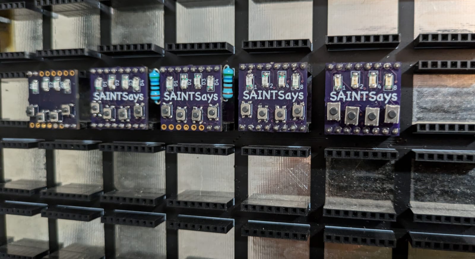
5:
The LEDs. The LEDs are a bit more sensitive than the Resistors in their orientation. On every LED there are some small Green highlights on one side. The Green side of the LED goes "inside the box" on the PCB.
The PCB silk screen has a while outline around 3 sides of the LED, this "box" design tells the expected polarity.
The SaintCON hardware hacking village should be able to help orient the LEDs if my explanation is not helpful.
Once the polarity is figured out, the LEDs solder on the same way as the Resistors.
Comments
Write a comment ...