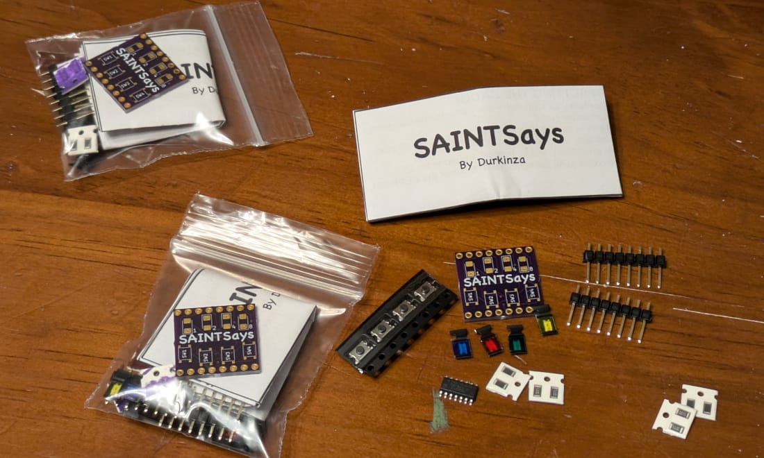
In each Saint Says package you should get a few components:
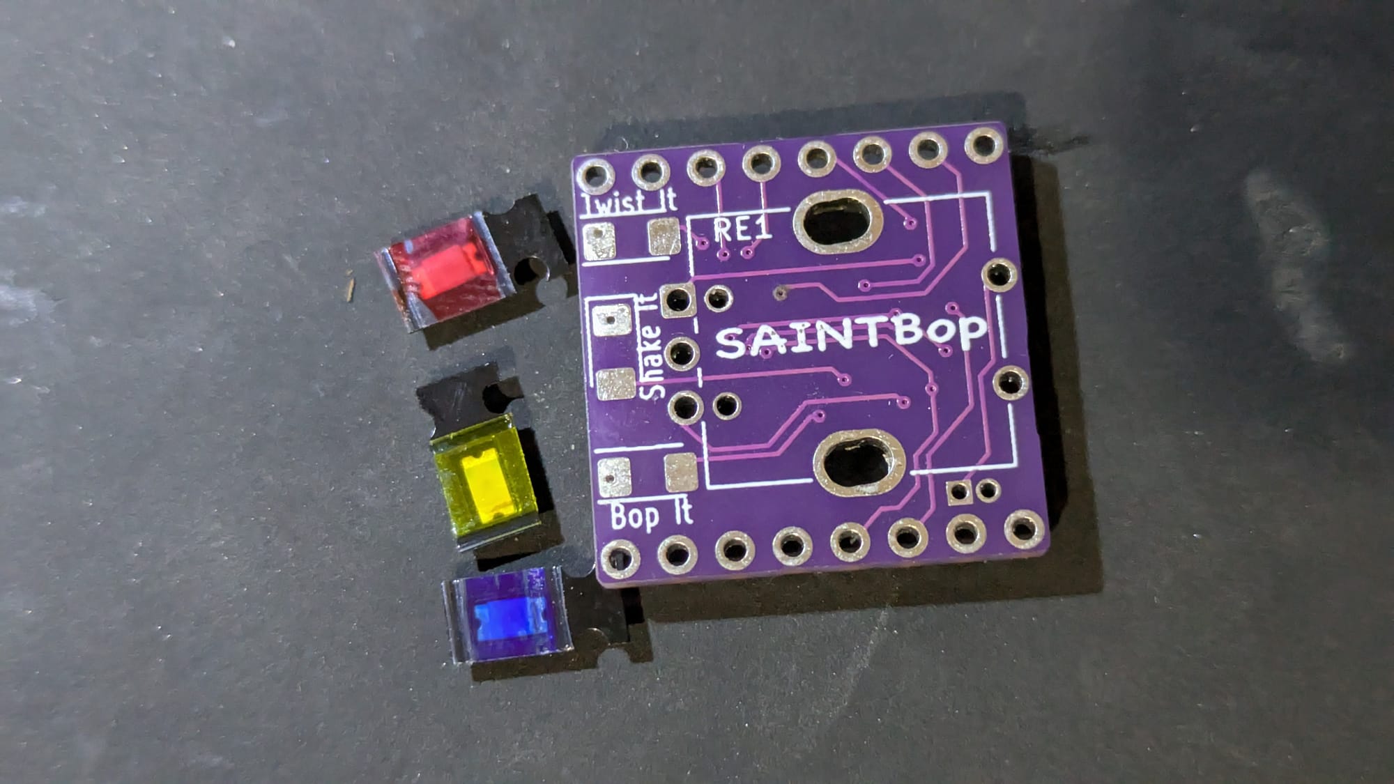
1 X Red LED
1 X Blue LED
1 X Yellow LED
3 X 510 Ohm Resistors
1 X Rotary Encoder
1 X Piezo Electric Buzzer
1 X Vibration Switch
2 X 8 pin headers
1 X ATTiny84a (pre-programmed)
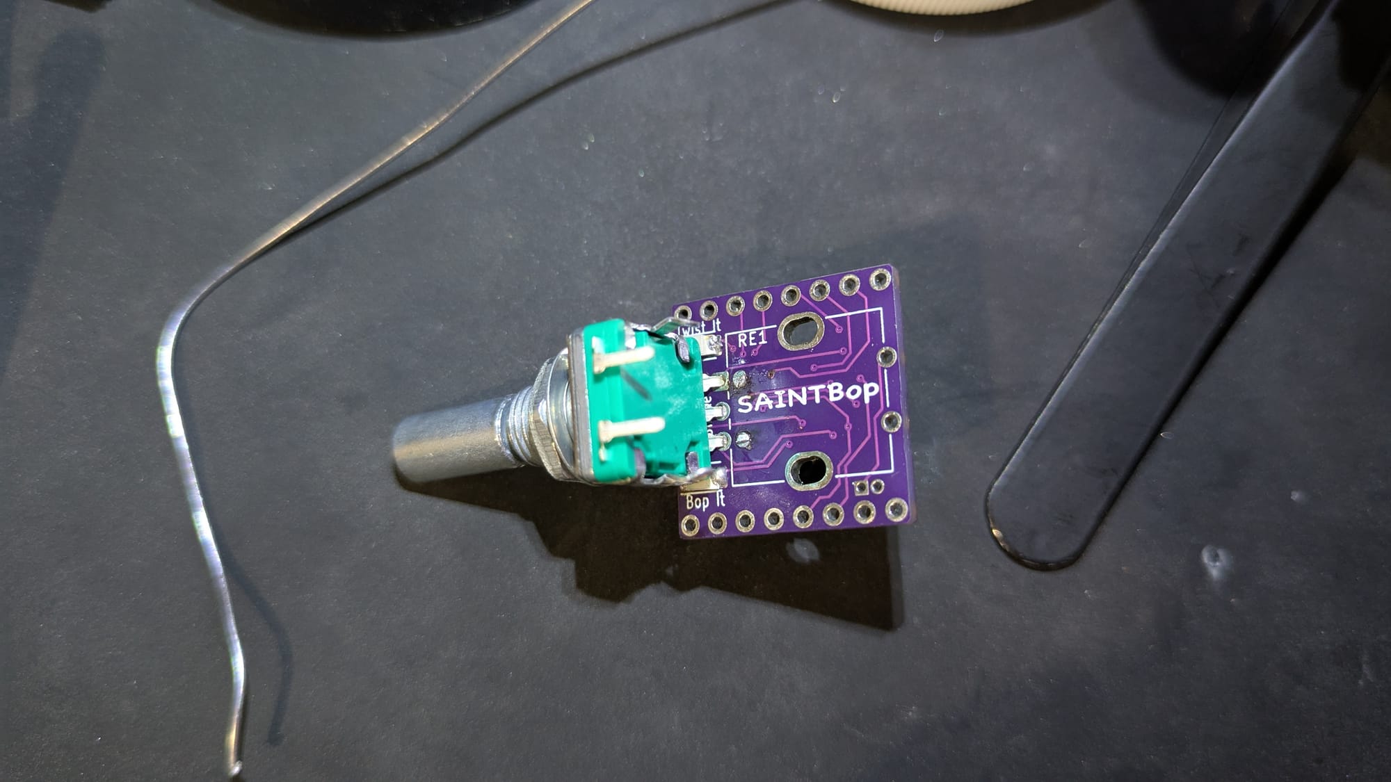
1 X SaintBop PCB
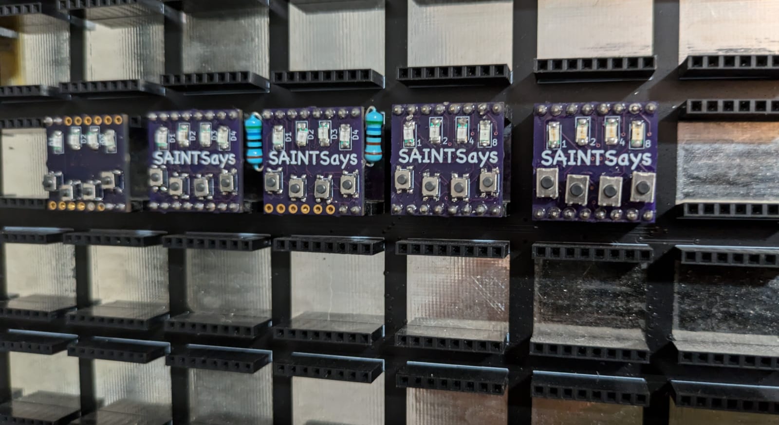
1: ATTiny
2: Resistors
3: LEDs
4: First half of Rotary encoder
5: Piezo Buzzer
6: Back half of Rotary Encoder
7: 8 pin Headers
8: Vibration Switch
As always with soldering, it's often easier to start with the smallest components first.
1: ATTiny84a
I would recommend starting with the ATTiny84a chip first.
To start, add a small amount of solder to the pin1 on the PCB, this pin is noted with the Arrow on the PCB silkscreen.
On the ATTiny84a chip there is small divot or bump on the chip that indicates pin1.
While keeping the pin1 solder liquid, lineup the ATTiny on the PCB and let the solder cool once you have the chip where you want it.
I like to solder the opposite side pin next to help spread any strengthen the hold of the chip on the PCB.
Next, you'll need to solder all of the other pins on the ATTiny./rest of the owl
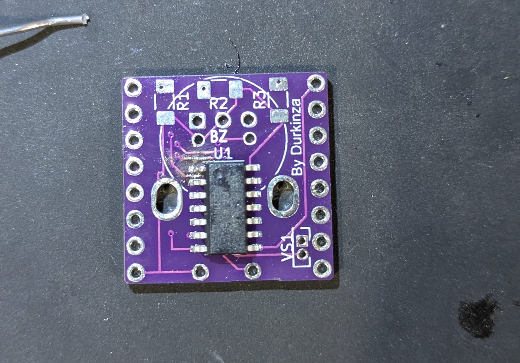
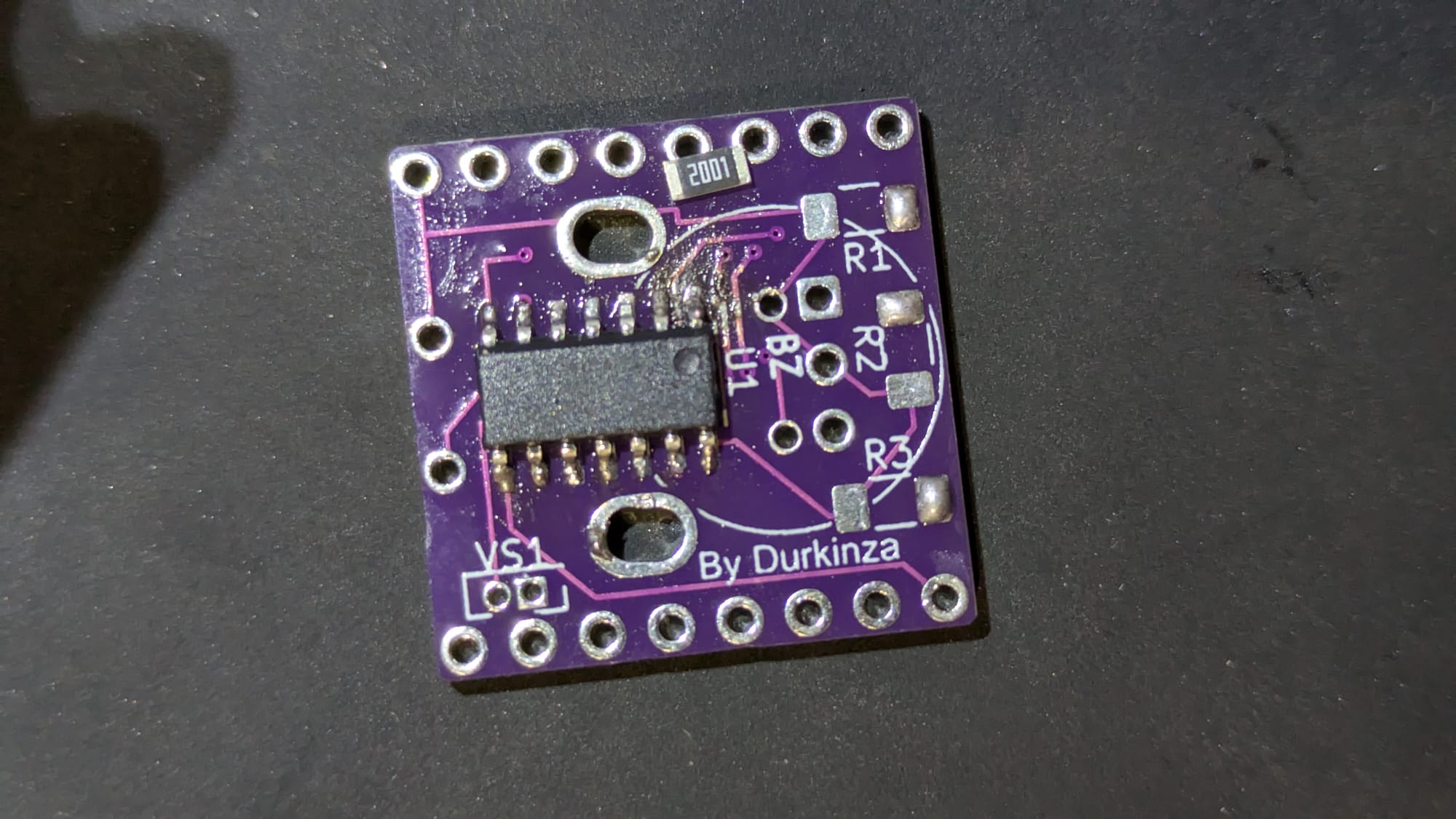
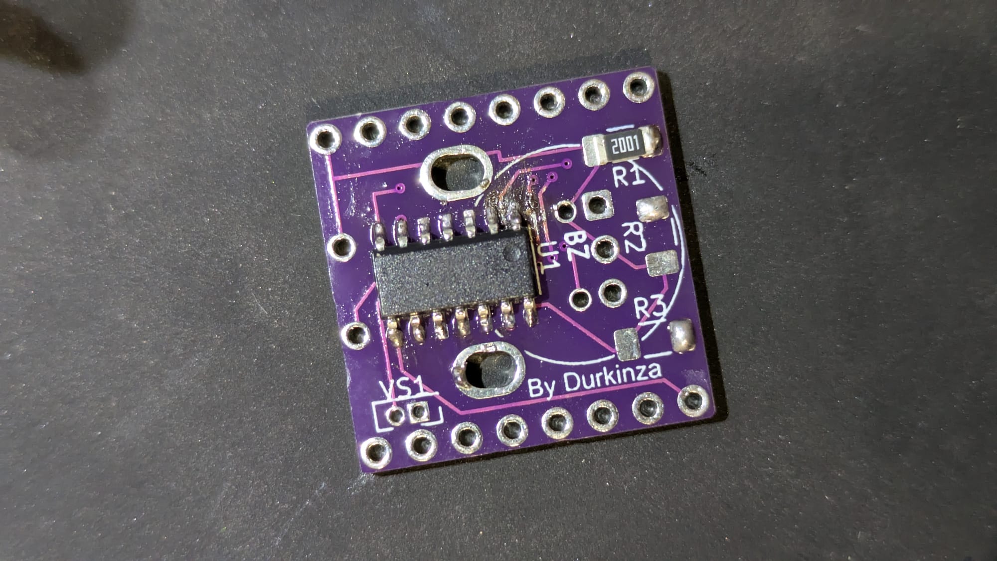
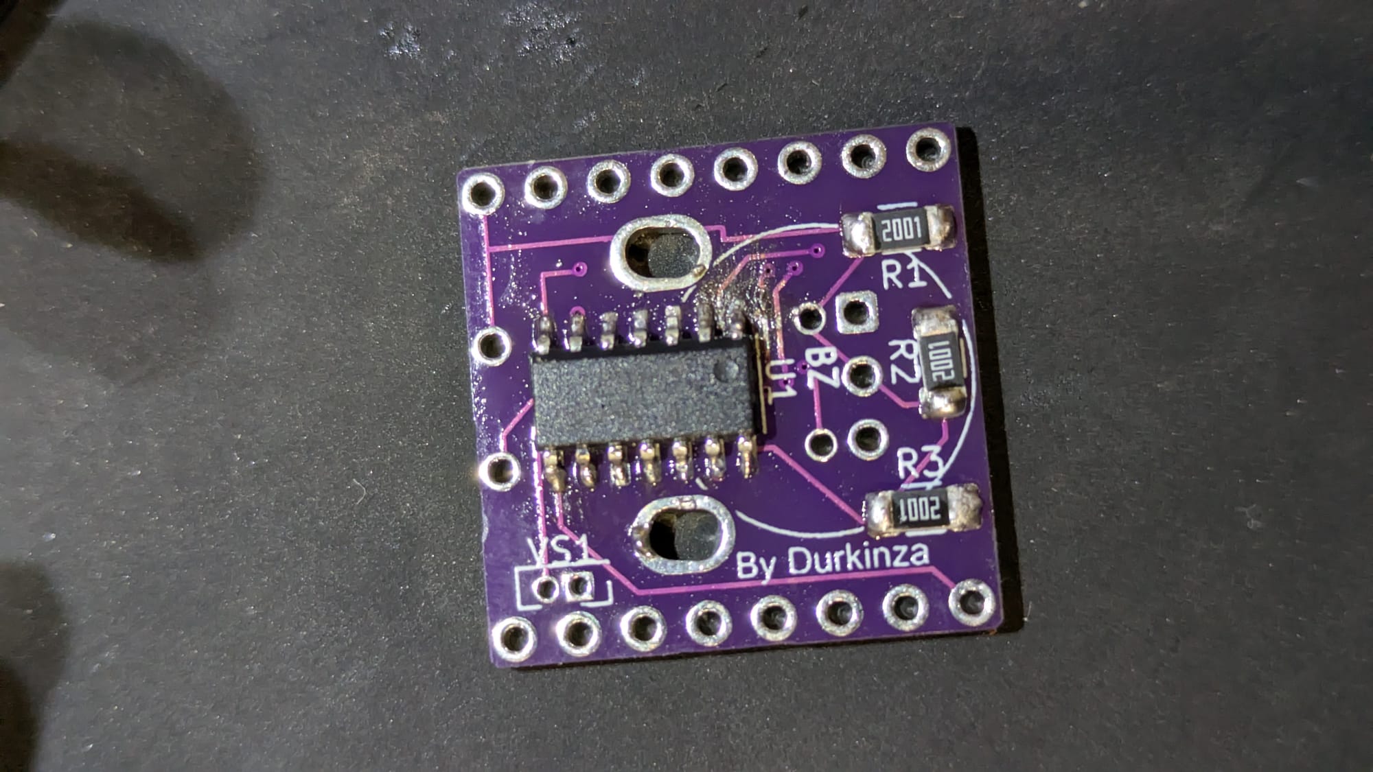
2: Resistors
I like to get the Resistors on the back soldered on next while you still have a smooth PCB on one side.
This can be done pretty smoothly by adding some solder to one of the two pads for each resistor.
while keeping the solder liquid, push the resistor into the wet solder and it should get pulled in. Then solder the other side of the resistor when you have it how you want it.
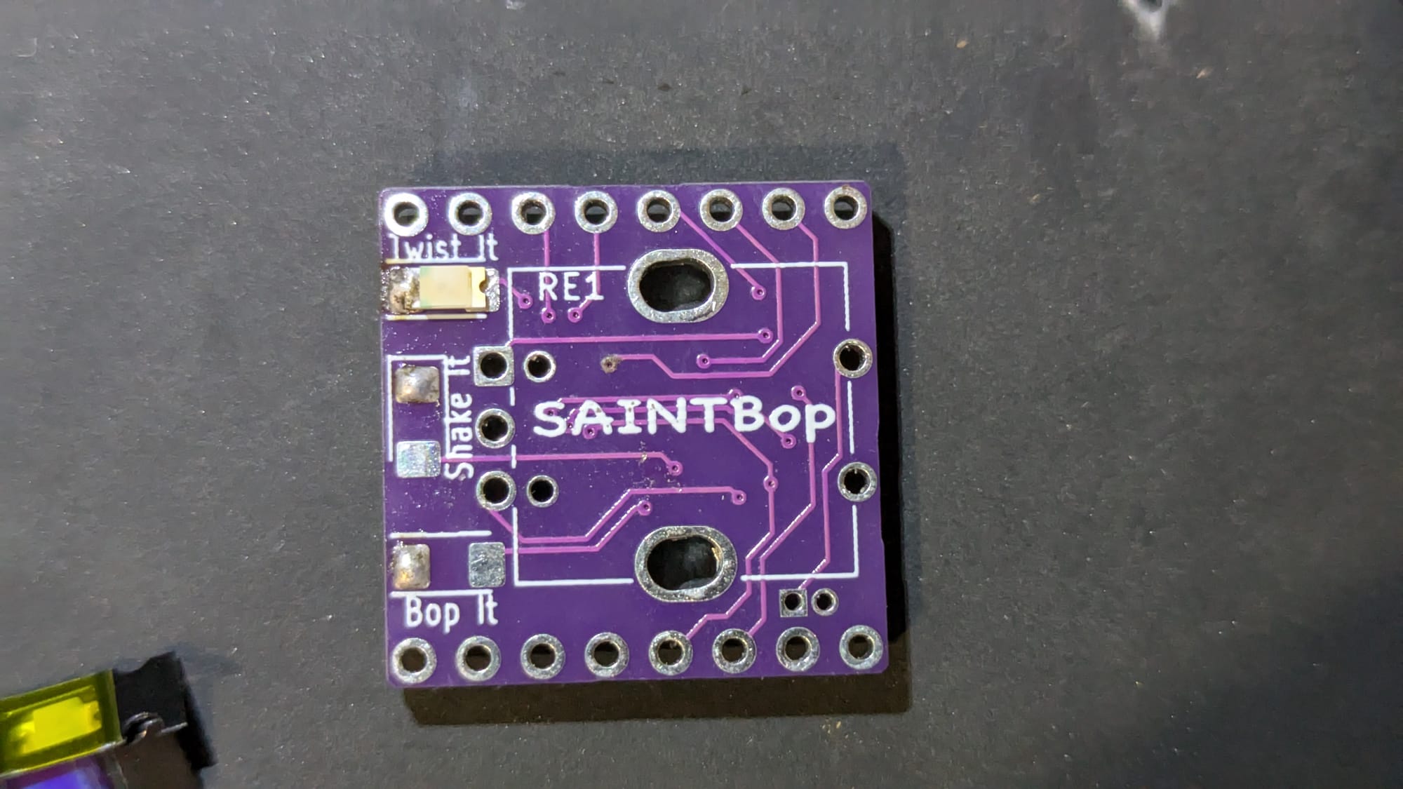
3: LEDs
I sometimes like to solder the Headers in now, and then the headers will keep the PCB flat off the table while you solder on the rest of the top components.
However, since the Resistors and ATTiny are pretty close to the same size and they support the board rather well I think it's better to leave the headers off. This also gives you a bit more space to solder on the rest of the components.
LEDs are directional and need to face a specific way when soldering them on.
If you look closely at the top of the LED, there is a green indicator on one side.
If you're unable to see the indicator, then there is also a green T on the bottom of the LED that can help orient it.
For the Twist and Bop LEDs, the Green indicator should be close to the edge of the PCB. Or if you're using the T indicator, the T should point to the edge of the PCB.
For the Shake LED, the Green indicator should be closer to the Twist LED, and the T should point to the Twist LED.
As for the order of colors for the LEDs, it doesn't matter much, but I like to keep the red and blue as the outside LEDs.
4: First half of Rotary Encoder
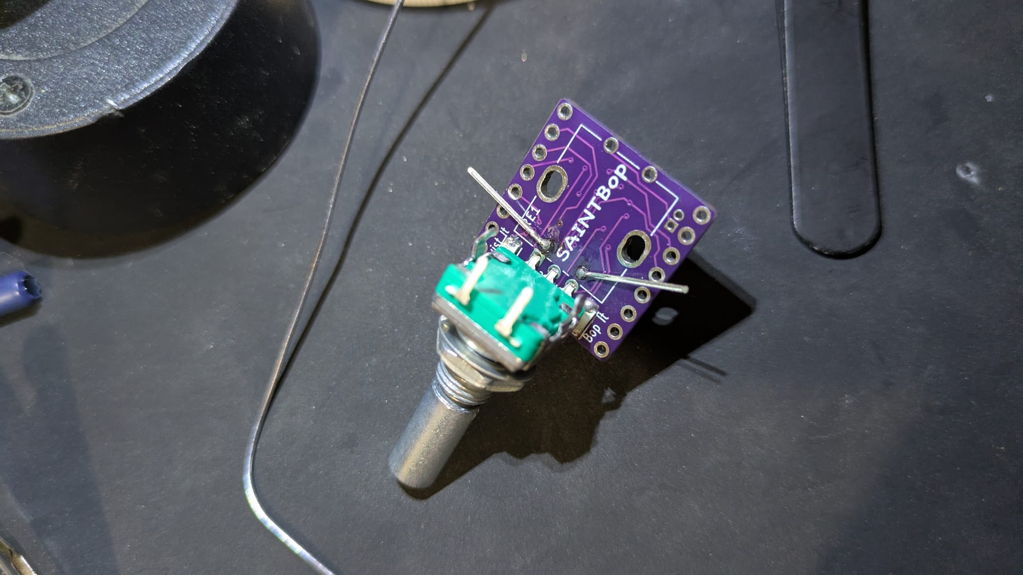
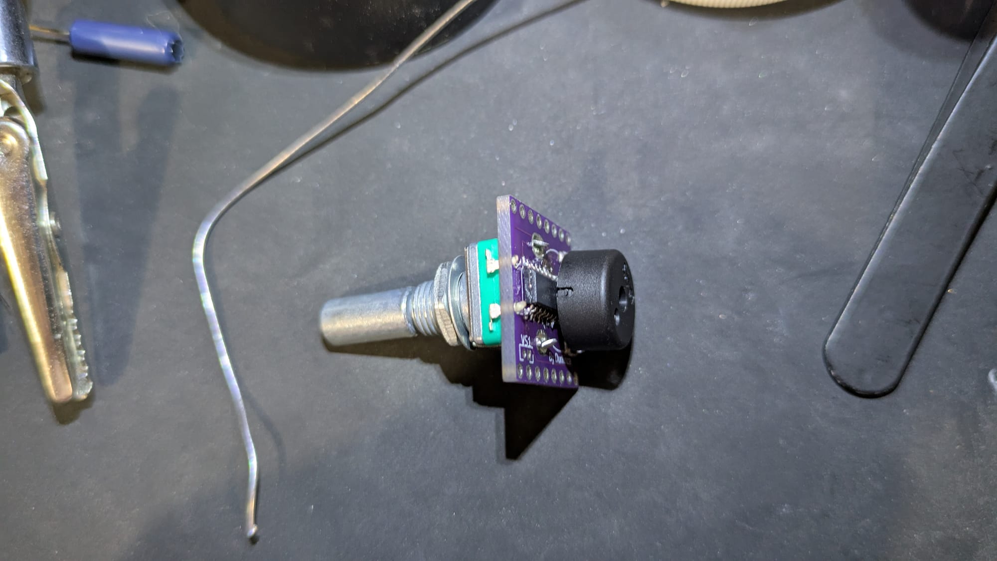
You may have noticed that the pins for the Buzzer are covered by the Rotary Encoder, and the pins for the Rotary Encoder are covered up by the Buzzer.
So how do you solder this?
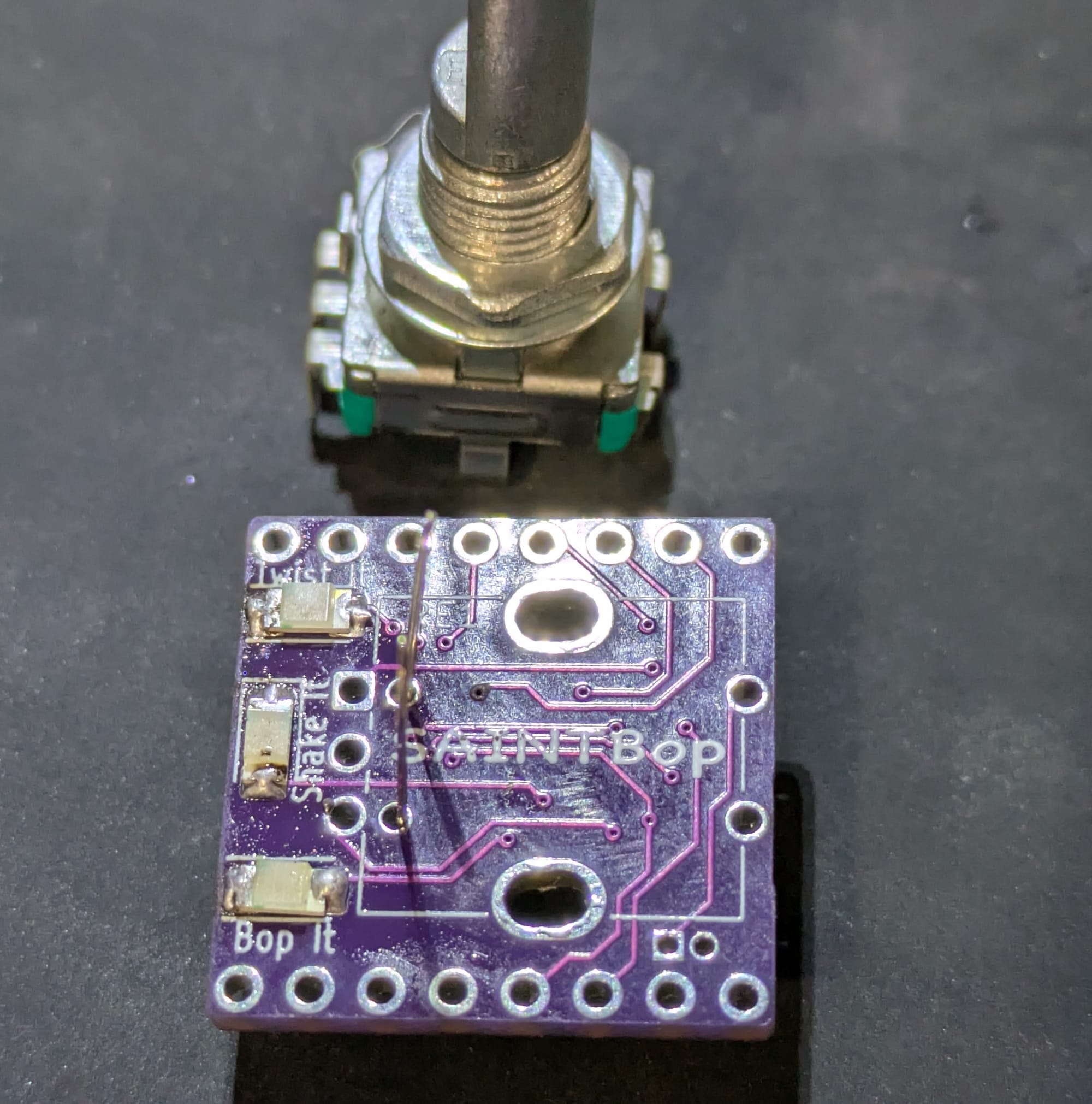
Buzzer pins are hidden by Rotary Encoder
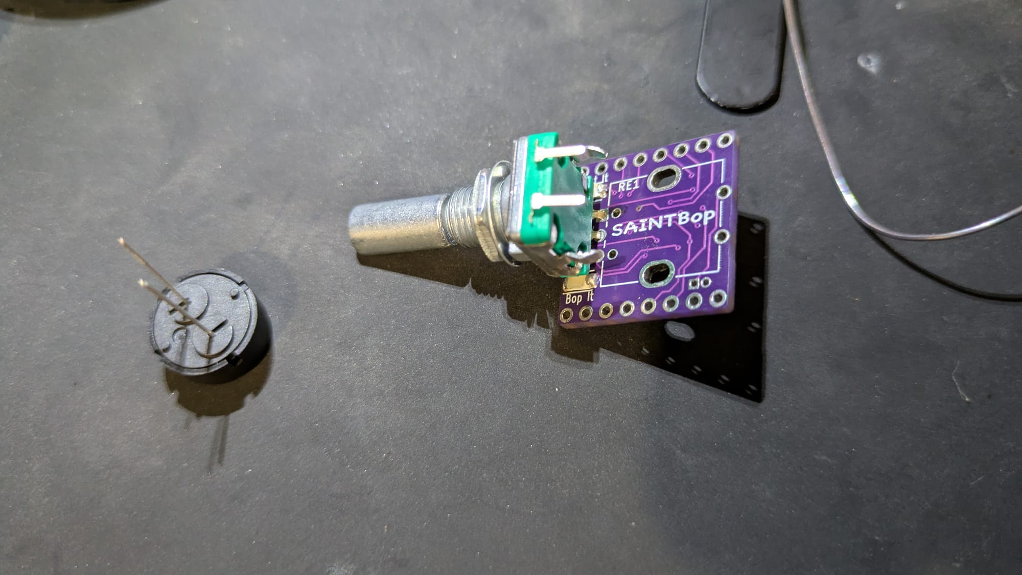
The solution here is to solder the 3 pins of the Rotary encoder first, and then bend the component out of the way while you solder the buzzer.
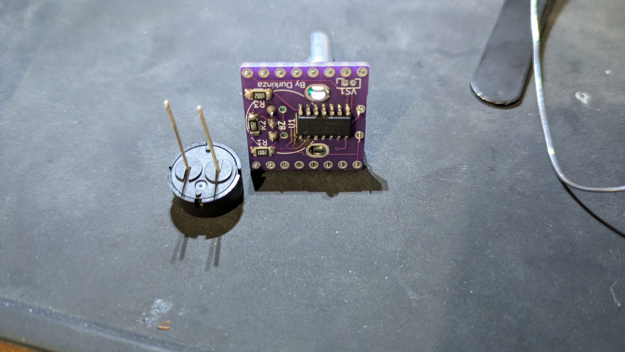
5: Piezo Buzzer
Now that half of the Rotary Encoder has been soldered and is bent out of the way, the Buzzer can be soldered in.
The Buzzer doesn't have polarity, so it doesn't care which direction the pins go in.
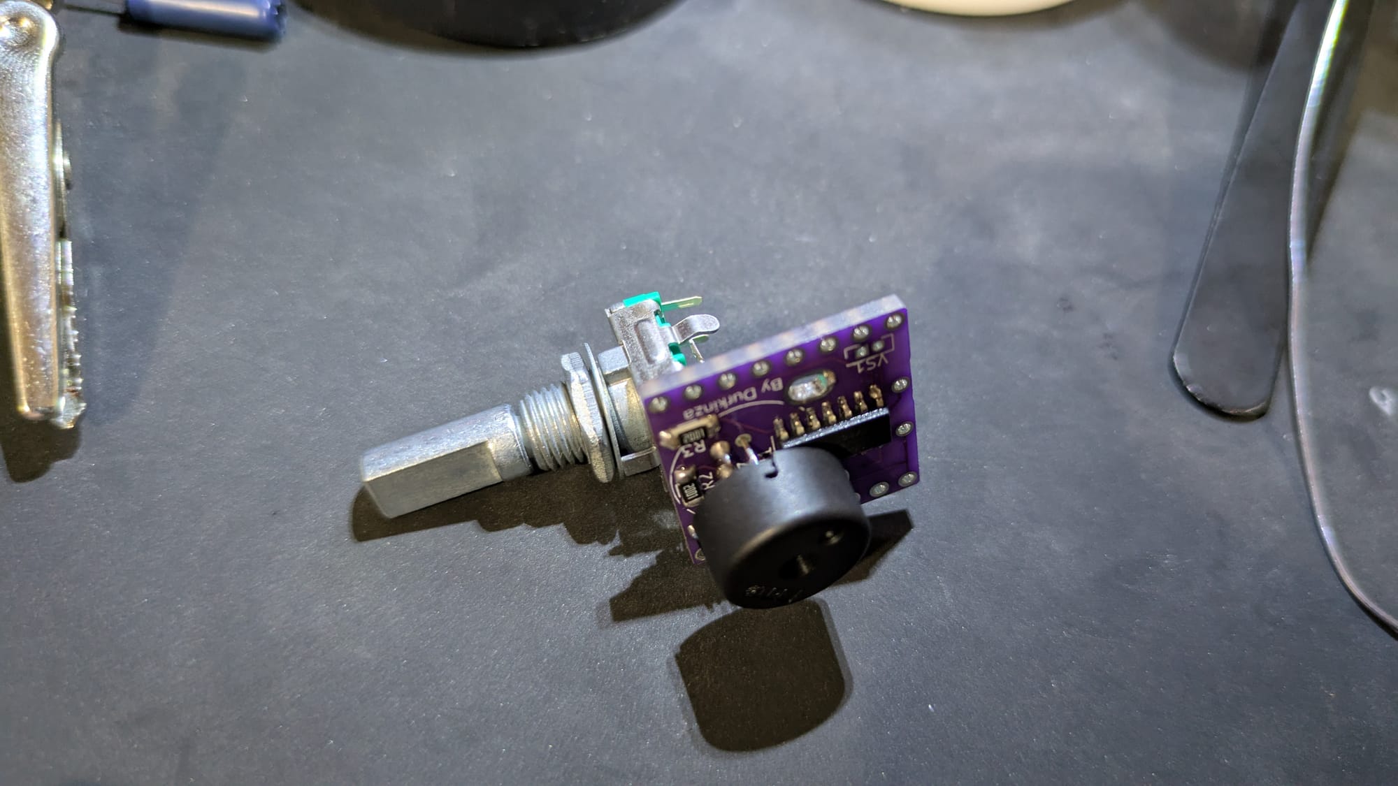
Be sure to clip off the excess pin length of the Buzzer, or else the Rotary Encoder won't be able to fit back in.
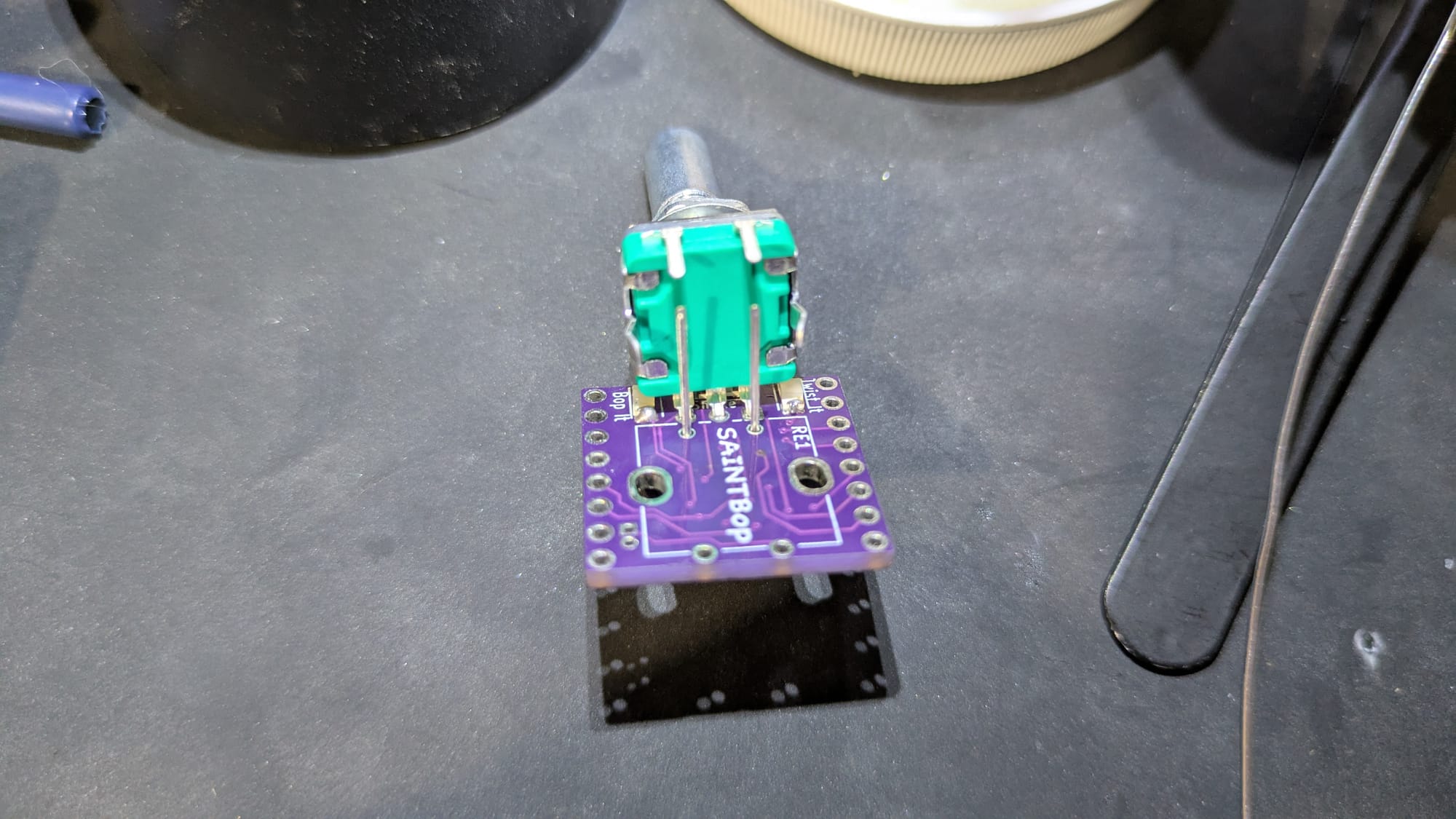
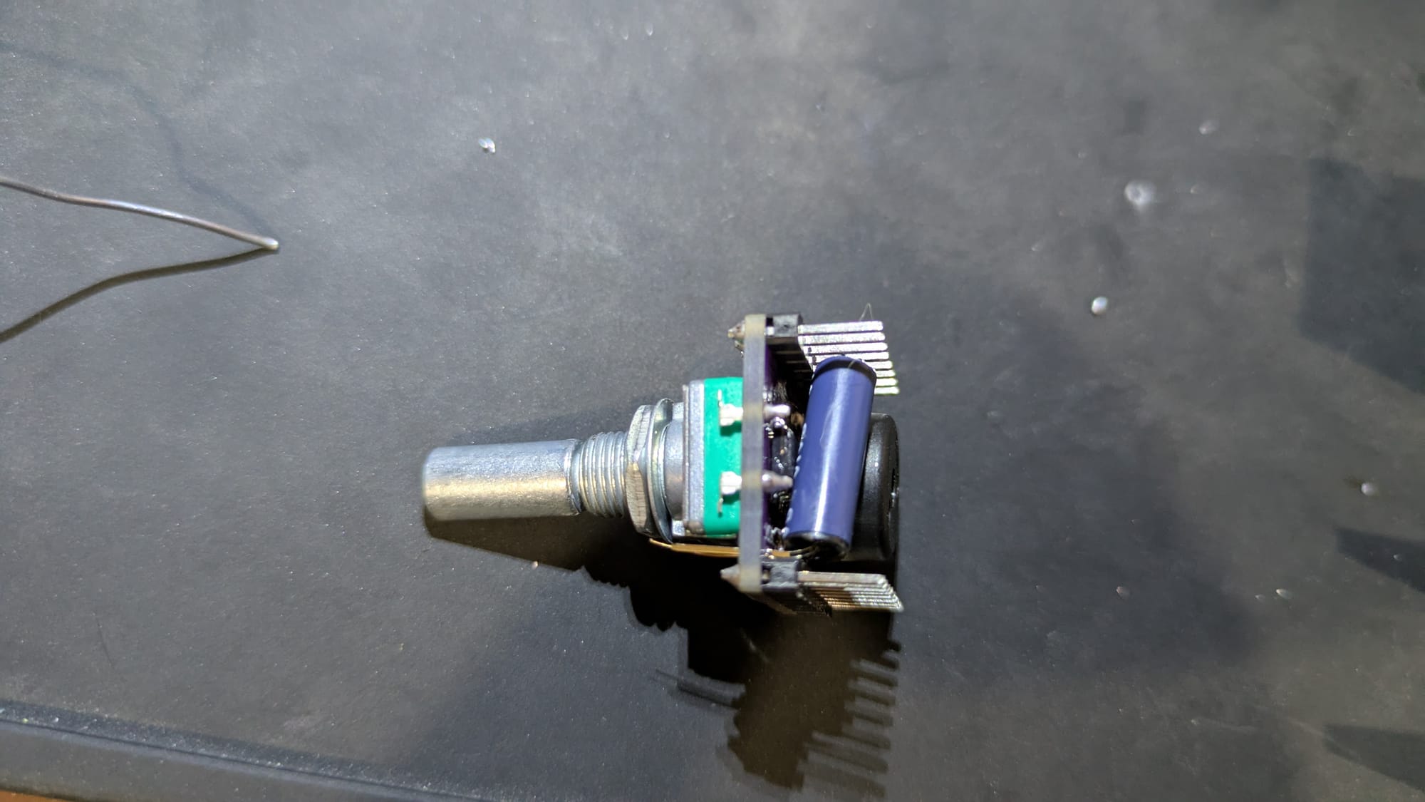
6: Second half of Rotary Encoder.
Now that the buzzer is in, the Rotary Encoder can be bent back to it's place and soldered in the rest of the way.
While the large side pins of the Rotary Encoder could be soldered in for more stability, they don't serve any functional purpose to the badge. If you have extra solder and you play a bit more aggressive they can be filled in.
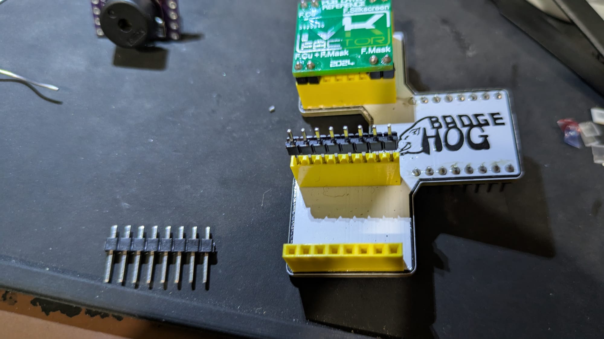
7: Headers
Some people may prefer to skip to step 8 here if they have already solder in the headers, or if they would like more space to solder the Vibration switch before soldering on the headers.
I find it easiest to solder in the header when you have a badge insert available.
Placing the headers into the inserts and then you can just place the PCB ontop and let gravity hold everything together while you solder.
8: Vibration switch
Finally the Vibration switch can be solder on. Since the Vibration switch is to tall to stick directly out, you'll need to leave some extra space on the pins to allow the header to bend over.
I like to solder this switch in last to help with gauging the amount of pin length to leave to bend the switch over.
The Vibration switch is not directional, so it doesn't matter which direction the pins go in.
Comments
Write a comment ...